
Published November 10, 2026
Building an Infrastructure-Less Multi-Node RF Communication Network: ESP32 Architecture and Node Synchronization
1. Introduction & Design Choices
In many field robotics and multi-node embedded applications, relying on centralized Wi-Fi routers or cellular infrastructure introduces a single point of failure. If the central access point drops or moves out of range, communication across the entire system breaks down.
The goal of this project (Swarm Sync) was to design and bench-test a lightweight, infrastructure-less RF communication network capable of coordinating multiple hardware nodes for scheduled near-simultaneous execution. Instead of relying on heavy IP-based network stacks, I chose a direct radio-frequency approach using ESP32-WROOM-32 microcontrollers paired with nRF24L01+ (PA/LNA) 2.4 GHz RF transceivers.
Why this stack?
- Deterministic Control: The nRF24L01 operates in the 2.4 GHz ISM band using the Enhanced ShockBurst (ESB) protocol, handling packet framing, CRC error checking, and automatic acknowledgments in hardware.
- Processing Overhead: The ESP32 provides dual-core processing power and hardware SPI buses, allowing the master node to handle packet routing, timing calculations, and serial debugging without blocking radio transmissions.
- Infrastructure-Less vs. Decentralized Topology: Unlike Wi-Fi or cellular systems that depend on external routers or base stations, this network operates over direct point-to-multipoint 2.4 GHz RF links. Architecturally, the bench-tested prototype uses a coordinator-driven (master–worker) topology rather than a fully decentralized peer-to-peer mesh: a designated Master/Coordinator Node serves as the local reference clock and command dispatcher, while Worker Nodes independently track clock offsets and execute scheduled actions locally.
2. Final System Architecture
The bench-tested prototype consists of 1 primary Master/Coordinator Node and 2 Slave/Worker Execution Nodes (Slave Node 01 and Slave Node 02) communicating over dedicated 2.4 GHz RF pipes (with hardware pipe support expandable up to 5 worker nodes per master).
Block Diagram Overview
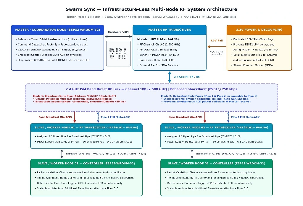
Figure 1: Swarm Sync — 1 Master & 2 Slave Nodes RF Architecture Block Diagram
|
Subsystem / Node |
Core Hardware |
Interface & RF Pipe Configuration |
Primary Engineering Role |
|
Master / Coordinator Node |
ESP32-WROOM-32 + nRF24L01+ (PA/LNA) |
Hardware VSPI (MOSI GPIO 23, MISO GPIO 19, SCK GPIO 18, CSN GPIO 5, CE GPIO 4); Broadcast Pipe “SYNC0” (0xFF) |
Maintains local 32-bit millis() reference clock, packages 14-byte SyncPacket payloads, and dispatches future execution timestamps. |
|
3.3V RF Power & Decoupling Stage |
Dedicated 3.3V Step-Down Regulator + 10 µF Electrolytic & 0.1 µF Ceramic Capacitors |
Soldered directly across VCC and GND pins of each nRF24L01+ module with shared common ground |
Supplies clean 3.3V current during PA/LNA transmission bursts (up to 115 mA), preventing voltage sag on the ESP32 onboard LDO. |
|
2.4 GHz ISM Band RF Link |
Nordic Enhanced ShockBurst (ESB) Baseband |
Channel 100 (2.500 GHz), 250 kbps air data rate, RF24_PA_LOW for bench testing |
Broadcast mode disables Auto-ACK to prevent ACK collisions; telemetry mode polls Pipe 1 and Pipe 2 sequentially (expandable to Pipe 5) with Auto-ACK enabled. |
|
Slave / Worker Nodes (Slave Node 01 & Slave Node 02) |
ESP32 MCU + nRF24L01+ Transceiver |
Hardware VSPI; listens on Broadcast Pipe “SYNC0” and dedicated Node Pipe (Pipe 1 and Pipe 2; scalable to Pipe 5) |
Validates packetSeq and checksum, calculates local clock offset relative to masterTimeMs, and triggers scheduled near-simultaneous GPIO/LED action at execTimeMs. |
Role of Each Component
- Master Node (ESP32): Acts as the local reference clock and command dispatcher. It packages state commands alongside a future execution timestamp and broadcasts them to the worker nodes.
- Communication Link (nRF24L01+ via SPI): Interfaces with the microcontrollers over the hardware SPI bus (MOSI, MISO, SCK, CSN, and CE). Per the nRF24L01+ Product Specification, the transceiver supports payloads up to 32 bytes and is configured here at an air data rate of 250 kbps (the lowest rate supported by the chip, which improves receiver sensitivity to −94 dBm for extended link margin).
- Worker Nodes: Listen on assigned reading pipes, validate incoming packet sequence numbers and checksums, synchronize their local millisecond timers against the Master Node’s clock offset, and trigger hardware actions for scheduled near-simultaneous execution when the target timestamp is reached.
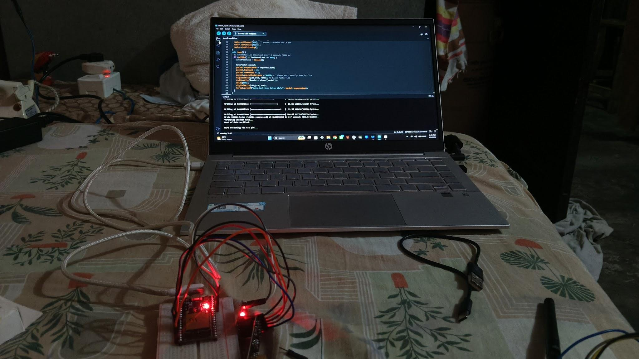
Figure 2: Bench-tested Swarm Sync hardware setup (1 Master Node and 2 Slave/Worker Nodes using ESP32-WROOM-32 and nRF24L01+ PA/LNA modules) showing near-simultaneous red GPIO indicator LED triggers under bench-test conditions and the Arduino IDE (v2.3.10) firmware upload session (sketch_sep8b.ino).
3. Firmware & Synchronization Logic
When broadcasting a command to multiple nodes over RF, slight variations in packet arrival time (due to retries or sequential polling) can cause nodes to execute commands out of sync. To solve this, the C++ firmware separates packet reception from command execution using a shared timestamp structure.
Data Packet Structure
To keep transmission overhead minimal and stay well within the nRF24L01’s 32-byte limit, the firmware packs all data into a tightly aligned C++ struct:
#include <SPI.h>
#include <nRF24L01.h>
#include <RF24.h>
// Define payload structure (14 bytes total, within nRF24L01+ 32-byte FIFO limit)
struct __attribute__((packed)) SyncPacket {
uint8_t nodeID; // Target node (0xFF for broadcast)
uint8_t commandID; // Action code to execute
uint32_t masterTimeMs; // Master’s current millis() at transmission
uint32_t execTimeMs; // Target future timestamp (ms) for scheduled execution
uint16_t packetSeq; // Sequence counter to drop duplicate packets
uint16_t checksum; // Simple XOR validation check
};
Master Node Dispatch Logic
Instead of instructing Slave Nodes to execute a command immediately upon reception, the Master Node defines a future execution delay window in milliseconds (execDelayMs, e.g., 50 ms or 100 ms ahead of masterTimeMs) and transmits the target millisecond timestamp (execTimeMs) using the TMRh20 RF24 library:
RF24 radio(4, 5); // CE (GPIO 4), CSN (GPIO 5) pins on ESP32
const byte broadcastAddress[6] = “SYNC0”;
uint16_t seqCounter = 0;
void broadcastSyncCommand(uint8_t cmd, uint32_t execDelayMs) {
SyncPacket pkt;
pkt.nodeID = 0xFF;
pkt.commandID = cmd;
pkt.masterTimeMs = millis();
pkt.execTimeMs = pkt.masterTimeMs + execDelayMs;
pkt.packetSeq = ++seqCounter;
pkt.checksum = (pkt.commandID + pkt.packetSeq) ^ 0xAAAA;
radio.stopListening();
// Multicast write (third parameter = true disables Auto-ACK for this payload)
radio.write(&pkt, sizeof(SyncPacket), true);
radio.startListening();
}
Note on Timing Units in the Bench-Test Firmware (execDelayMs vs. executionDelayUs): The multi-node clock-offset implementation above operates in milliseconds (ms) via millis(), using execDelayMs = 50 (a 50 ms scheduling window) to compute execTimeMs. In the earlier single-hop bench test sketch visible on the laptop screen in Figure 2 (sketch_sep8b.ino), this exact same 50 ms scheduling delay was expressed in microseconds (µs) as packet.executionDelayUs = 50000 (50,000 µs = 50 ms), where each Slave Node waited 50,000 µs (50 ms) after packet reception before triggering its GPIO indicator LED. Using millis() and execDelayMs in the final firmware simplifies 32-bit timestamp arithmetic alongside masterTimeMs while maintaining the same 50 ms (50,000 µs) execution window.
Worker Node Synchronization & Collision Avoidance
If multiple nodes attempt to send an automatic acknowledgment (Auto-ACK) on the same pipe at the exact same microsecond, their RF packets collide at the Master receiver.
To avoid this:
- Broadcast vs. Polling: Broadcast commands disable hardware Auto-ACK (write(&pkt, sizeof(pkt), true)), while individual status checks poll nodes sequentially by nodeID with Auto-ACK
- Clock Offset Compensation: Each worker node calculates the offset between its own internal millis() timer and pkt.masterTimeMs, queuing the action until the compensated clock hits pkt.execTimeMs:
int32_t clockOffset = 0;
bool actionPending = false;
uint32_t localTargetTime = 0;
uint8_t pendingCmd = 0;
void handleIncomingRadio() {
if (radio.available()) {
SyncPacket pkt;
radio.read(&pkt, sizeof(SyncPacket));
uint32_t now = millis();
// Update local clock offset relative to master
clockOffset = (int32_t)(now – pkt.masterTimeMs);
// Convert master’s execution timestamp to local node time
localTargetTime = pkt.execTimeMs + clockOffset;
pendingCmd = pkt.commandID;
actionPending = true;
}
}
void loop() {
handleIncomingRadio();
if (actionPending && (int32_t)(millis() – localTargetTime) >= 0) {
executeHardwareAction(pendingCmd);
actionPending = false;
}
}
4. Hardware Issues & Troubleshooting
Building the system on a breadboard quickly exposed the gap between theoretical code and real-world RF electronics. Here are three major issues encountered during testing and how they were resolved:
Issue 1: Intermittent Packet Drops During High-Power Transmission
- Symptom: The ESP32 correctly initialized the nRF24L01+ PA/LNA modules over SPI, but transmissions would randomly fail or cause the radio module to lock up when transmitting at high power.
- Diagnosis: Using a multimeter and serial status dumps via RF24::printDetails(), I traced the issue to voltage sag on the ESP32’s onboard 3.3V regulator. Per the Nordic nRF24L01+ Product Specification, while the base transceiver IC draws 11.3 mA in TX mode at 0 dBm, modules equipped with a Skyworks / RFaxis RFX2401C 2.4 GHz PA/LNA front-end IC (nRF24L01+PA+LNA module specification) draw peak current spikes of up to 115 mA during +20 dBm transmission bursts, causing transient voltage sag and power supply noise that corrupts the sensitive RF transceiver.
- Fix & Result: I soldered a 10 µF electrolytic capacitor in parallel with a 1 µF ceramic decoupling capacitor directly across the VCC and GND pins of each nRF24L01 module, and powered the RF modules from a dedicated 3.3V step-down regulator with a shared common ground. Packet success rates immediately stabilized.
Issue 2: Close-Range Receiver Saturation
- Symptom: When testing two stationary breadboard nodes positioned less than 30 cm apart on the workbench with the PA/LNA modules set to maximum output power (RF24_PA_MAX), the majority of transmitted sync pulses were dropped or failed CRC validation despite verified SPI wiring.
- Diagnosis: At sub-30 cm separation, high-power radiation from the external PA stage saturated the receiver’s Low Noise Amplifier (LNA) front-end, clipping the incoming 2.4 GHz signal.
- Fix & Result: Lowering the output power in firmware via setPALevel(RF24_PA_LOW)for indoor bench testing and increasing physical antenna separation to 0.5–1.5 m across the workbench eliminated front-end saturation, achieving consistent, drop-free packet reception across both Slave Nodes during repeated 3-second broadcast test cycles on RF Channel 100 (2.500 GHz).
- Symptom: When all nodes listened to the same address pipe with hardware Auto-ACK enabled, the Master Node frequently reported failed transmissions even though the worker nodes actually received the payload.
- Diagnosis: All worker nodes were transmitting their hardware ACK packets back to the Master at the exact same instant, garbling the return signal.
- Fix & Result: I split communication into two modes: unacknowledged multicast (setAutoAck(false) or dynamic no-ACK writes) for broadcast sync triggers, and staggered time-division polling on unique node pipes (Pipe 1 and Pipe 2 for the two bench-tested Slave Nodes, expandable up to Pipe 5) for telemetry readbacks.
5. Demonstrated Results vs. Future Scope
What Has Been Demonstrated (Bench-Tested)
- Hardware-Level Synchronization: Successfully transmitted structured C++ command payloads from an ESP32 master node to multiple receiver nodes over 2.4 GHz RF without relying on Wi-Fi or external routers.
- Scheduled Near-Simultaneous Execution: Verified that timestamp-offset scheduling allows the 2 Slave Nodes to execute state changes (such as GPIO/LED triggers) in scheduled near-simultaneous alignment under the bench-test conditions while avoiding ACK packet collisions.
- Hardware Stability: Resolved SPI bus initialization glitches and 3.3V rail current spikes on nRF24L01+ PA/LNA transceivers for reliable benchtop operation.
- Bench Test Conditions & Measurement Scope: Bench validation was conducted indoors using 3 hardware nodes (1 Master/Coordinator Node and 2 Slave/Worker Nodes)assembled on breadboards and separated by 0.5 m to 1.5 m. All transceivers operated on RF Channel 100 (2.500 GHz) at a 250 kbps air data rate with RF24_PA_LOW output power and hardware Auto-ACK disabled on the broadcast pipe (radio.setAutoAck(false)). The Master Node transmitted periodic sync pulses every 3,000 ms (3 s) with a scheduled execution delay window of execDelayMs = 50 ms (equivalent to executionDelayUs = 50000 µs in the sketch_sep8b.ino bench test sketch). Scheduled near-simultaneous command execution across the Master and 2 Slave Nodes was verified under bench-test conditions via visual GPIO indicator LED triggering and serial monitor packet sequence logging (115200 baud); quantitative jitter profiling with a logic analyzer or oscilloscope is planned for the next validation phase.
Future Development Scope
While this architecture uses concepts relevant to multi-vehicle coordination, it has currently only been validated on stationary benchtop nodes. Before this system could be integrated into active UAV or mobile robotics platforms, several next steps are required:
- MAVLink Framing Integration: Transitioning from a custom 14-byte struct to standard MAVLink message framing, allowing the ESP32 RF bridge to interface directly with flight controllers running ArduPilot or PX4 via UART.
- Dynamic Mesh Routing: Expanding the firmware so that if a peripheral node loses direct line-of-sight with the Master Node, neighboring nodes can automatically relay the packet.
- RF Interference & Range Testing: Conducting outdoor line-of-sight range tests and measuring packet loss in noisy 2.4 GHz environments alongside active RC transmitters.
6. Technical References
- Nordic Semiconductor ASA: nRF24L01+ Single Chip 2.4 GHz Transceiver Product Specification v1.0— Enhanced ShockBurst (ESB) baseband protocol, 32-byte FIFO buffers, air data rates (250 kbps, 1 Mbps, 2 Mbps), receiver sensitivity (−94 dBm at 250 kbps), and base IC current draw (11.3 mA TX at 0 dBm).
- Skyworks Solutions / RFaxis: RFX2401C 2.4 GHz IEEE 802.15.4 / ZigBee / ISM RF Front-End IC (PA/LNA) Technical Summary& nRF24L01+PA+LNA Module Specification — External +20 dBm Power Amplifier and Low Noise Amplifier front-end stage characteristics and 115 mA maximum TX burst current draw at 3.3 V.
- Espressif Systems: ESP32-WROOM-32 Datasheet& ESP32 Technical Reference Manual — Dual-core MCU architecture, hardware VSPI bus pin multiplexing, and 32-bit hardware timer peripherals.
- TMRh20 (Avamander et al.): Optimized High-Speed nRF24L01+ Driver (RF24) C++ Library Documentation— Driver API reference for setPALevel(), setAutoAck(), unacknowledged multicast write(), and printDetails().
- Dronecode Foundation: MAVLink Developer Guide, ArduPilot MAVLink Basics, and PX4 Autopilot MAVLink Messaging Guide— Serial telemetry framing standards referenced for future flight-controller integration.
Related Posts
Key Takeaways
-
Developed an infrastructure-less RF communication network using ESP32 and nRF24L01+ modules for independent multi-node coordination. -
Implemented timestamp-based synchronization to enable scheduled near-simultaneous execution across multiple worker nodes. -
Improved RF communication reliability by resolving power instability, receiver saturation, and packet acknowledgment collisions. -
Designed a scalable master–worker architecture supporting multiple nodes through dedicated RF communication pipes. -
Successfully bench-tested synchronized multi-node execution, establishing a foundation for future UAV and mobile robotics integration.